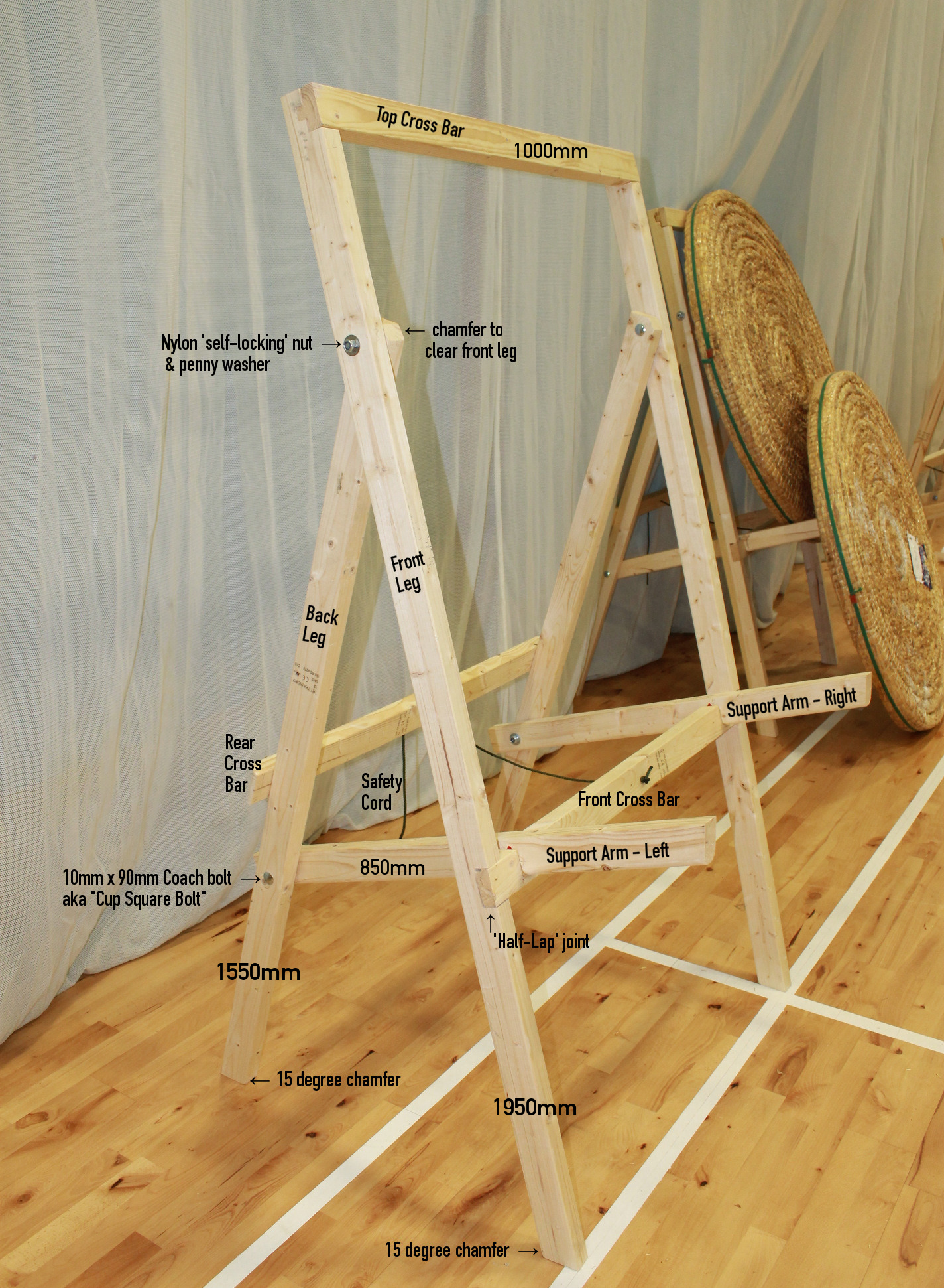
"Bonnyrigg" Archery Stands


Parts List, per stand
- CLS Timber, 63 x 38mm, 2400mm lengths, qty. 6 (Qty 5.5 if making several stands.)
- Cup Square Bolts (Coachbolts) 10mm or 12mm x 90mm long, qty.4
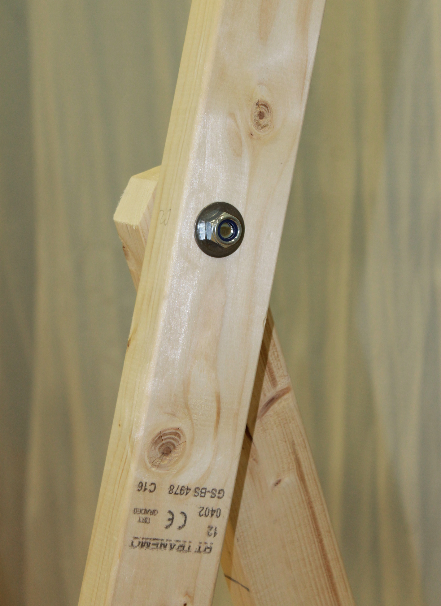
- Penny Washers, to fit coachbolts, qty. 12 Matching fibre/rubber washers if available.
- Lock-nuts, Nylon insert, to fit coachbolts, qty.4
- Wood screws, 6mm x 90mm long, qty. 8
- Wood screws, 6mm x 60mm long, qty. 4
- Cord, rope or webbing; approx 1m but allow a little extra for the knots if using thick rope

Notes

Wrap shaft of bolt with approx. four layers of masking tape (approx six inches long), to match or exceed the size of the threads.
Use a fibre washer if possible, or glue two penny washers together, either way, get the widest washer available.
A small patch of red paint on the front of the front cross bar can provide a useful "Tell-tale" to indicate that the support arms are not fully in place.
When the support arm is in place, draw a pencil line around the bottom of the support arm, on the front face of the front cross bar, then remove the support arm and paint almost up to pencil line. The same thing can be done on the sides of the support arm, where it would normally be inside the notch in the front cross bar.
(The photos explain this better than I can.)
Marking out / construction
- Fashion a rebate of approx. 25mm to the top of the front legs (Part F) and a matching rebate to either end of top cross-bar C.
- Measure c. 45mm down from top of back leg - Part B for bolt hole.
- Line up front and back legs (Parts F + B), drill bolt hole through both legs for top pivot.
- Measure up 550mm from the base of back leg B, for bolt hole to pivot the support arms. Adjusting this height will adjust the height of the boss, which will be necessary if the stand is built to a different width, or if your bosses are not 1230mm in diameter, which is the current competition standard. A slight counter-bore may be required to hide head of bolt, on the outside face of the leg, if a hex-head bolt is used.
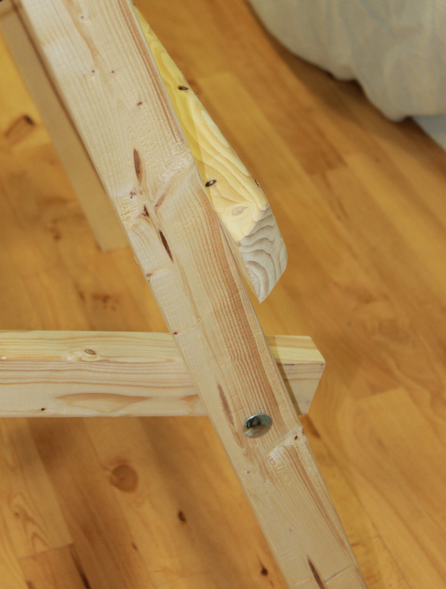
- Fit coach-bolt/cup-square bolt through front leg. A sharp tap with a hammer should settle the 'square' into the timber of the leg. Fit two washers + a fibre washer, then the back leg. When held upright, the chamfered feet should point in opposite directions, and when opened out, the feet should sit flat on the floor. Fit third washer, and loosely fit a temporary (plain) nut.
- The back legs require a slight chamfer at the top, otherwise the corner will protrude in front of the front legs. Stand the legs upright and fully open, and mark the protrusion with a pencil. Dissassemble the legs and remove the top corner of the back legs, as marked.
- Measure (68mm / 2) = 34mm (half the width of your timber) from back (rounded) end of support arm for bolt hole
- Fit coach-bolt/cup-square bolt through back leg. Fit two washers + a fibre washer, then a support arm, long edge uppermost. Fit third washer, and loosely fit a temporary (plain) nut. NB. The washers are intended to act as spacers between the various parts, fibre or rubber washers help to stop the joints swinging too freely.
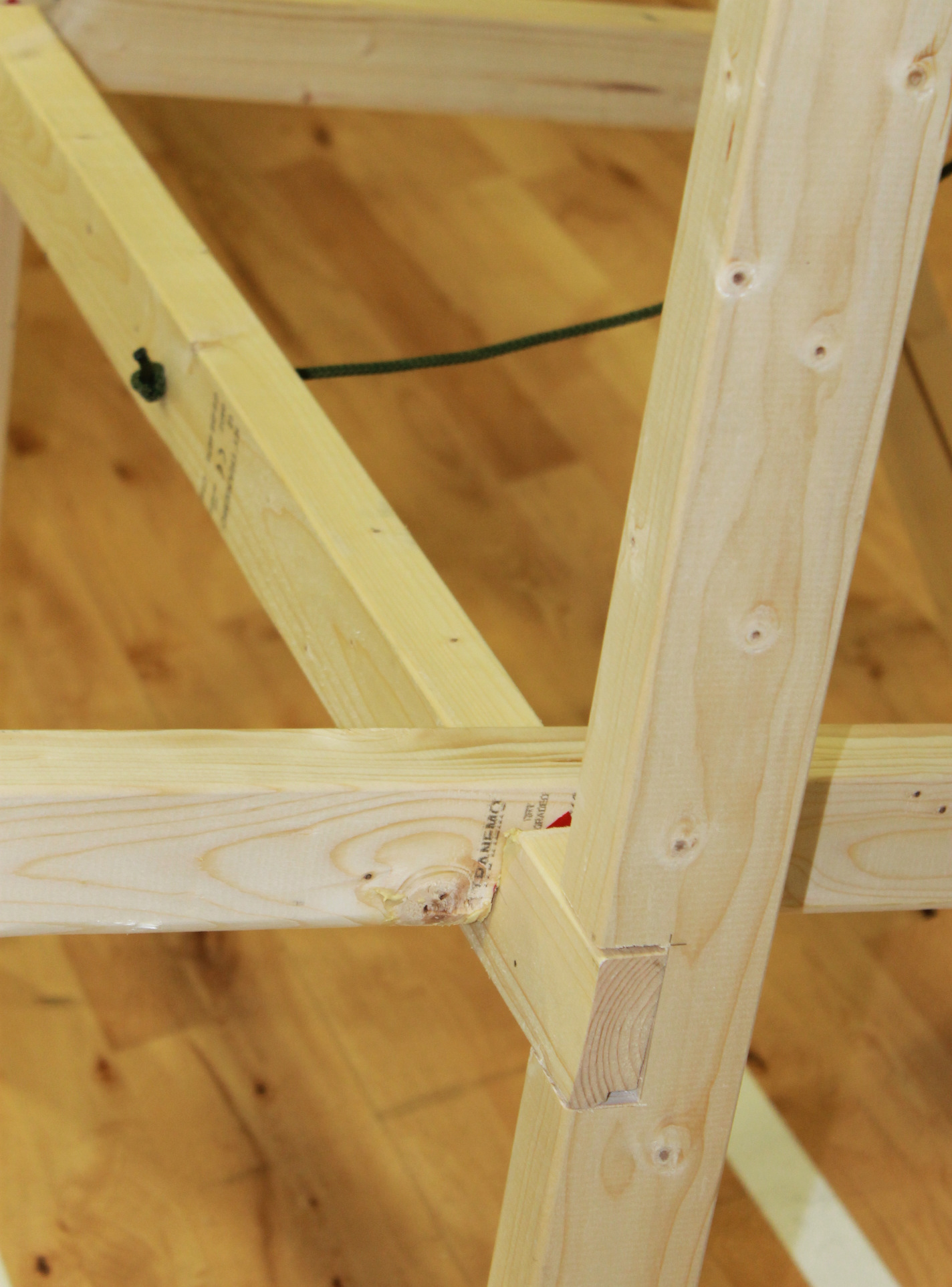
- Fit top cross-bar Part C. This should be a snug fit in the half-lap joint at the top of the front leg.
- Loosely fit the front cross-bar D, between front legs.
- Carefully open the frame ensuring that the feet are sitting flat on the ground. Lower the support arms so that they rest on top of the front cross-bar and mark the points of contact with a pencil.
- Remove the support arms and the front cross-bar. Square off the pencil marks and cut a rebate on each arm, and a pair of rebates on the cross-bar to match. Note that there will be a slight angle between the arms and the cross-bar, and the edges will need to be splayed out slightly if the two rebates are to mate easily. (Final adjustment will probably be necessary once the stand is fully assembled.)
- Ensure frame is folded, fit rear cross beam E, circa six inches / 150mm above the position of the front cross-bar.
- Open the stand, and fit a restraining rope. The rope should not be taught, as it is merely a safety feature to prevent the stand accidentally opening too far. For outdoor use, drill peg holes in all four feet, and dip the feet in an appropriate wood preservative.
- Both the front and back legs have chamfered feet - double check that these face in opposite directions before fitting locknuts to all bolts.
- All joints are intended to be screwed from the rear of the stand - this does mean that the length of most of the screws is critical, but dramatically reduces the chance of damaging an arrow through hitting a screw-head.
- Ensure all bolts are tight before use - ideally there should be a little resistance in each joint, to prevent accidental injury from swinging parts.